The cryogenic test facility at Oak Ridge National Laboratory’s Spallation Neutron Source (SNS) provided a unique environment for testing the performance of a 9 foot-tall tritium-compatible cryoviscous compressor pump prototype designed for the ITER tokamak. Initial testing, using deuterium to simulate tritium capture, occurred in late April. So far, the results show that a large portion of deuterium was successfully captured by the pump—a necessary part of the fuel recycling process in the ITER fusion reactor. The international ITER facility is now under construction in southern France; the US and other ITER partners are busy designing and fabricating components for the ITER machine.
“This is the first use of the cryogenic test facility for projects outside SNS,” said Sang-Ho Kim, group leader for superconducting LINAC systems in the research accelerator division at SNS. “Our group has been collaborating with the US ITER roughing pumps team for several years, planning for this testing and discussing related technical issues.”
The SNS cryogenic test facility was commissioned in 2013 for superconducting radio-frequency cavity testing and can provide refrigeration down to 4.5 Kelvin, or about -450 F, plus helium liquefaction at a flow rate of 240 liters per hour. These features contribute to an environment with temperatures, pressures and flow rates similar to the requirements of the ITER reactor.

Robert Duckworth, a researcher with the ORNL plasma technologies and applications group within the fusion materials and nuclear systems division, oversaw the cryoviscous compressor (or CVC) pump testing. “The SNS cryo facility worked great,” Duckworth said. “The SNS staff was very engaged and went above and beyond to assure that we had a positive test experience. The CVC performed well in its first full-scale test and was able to freeze deuterium with helium. We learned much that we can take and use for the final installation of the CVC at ITER.”
“SNS was generous with staff expertise, uninterrupted time and allowances for our testing schedule. We work best as a team, and this is a great example of drawing on our strengths as a laboratory,” said Mike Hechler, US ITER team leader for the vacuum auxiliary system and roughing pumps.
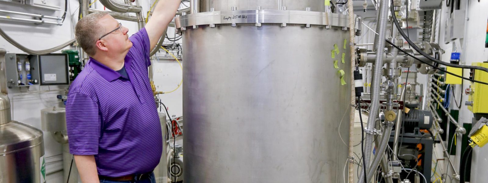
Major Tool and Machine in Indianapolis, Indiana fabricated the full-size cryoviscous compressor pump under contract to US ITER. The prototype is about 2500 pounds, 9 feet tall and 4 feet in diameter. In addition, valve box assembly, instrumentation, & controls were fabricated by Meyer Tool & Manufacturing in Oak Lawn, IL, and cryogenic transfer lines were fabricated by Eden Cryogenics of Plain City, OH. Besides Duckworth, the team includes Steve Meitner, who designed and oversaw fabrication of the CVC prototype and principal investigator Larry Baylor.
Ultimately, six cryoviscous compressor pumps will be manufactured and installed on the ITER machine. The primary fusion fuels that will be used on ITER are deuterium and tritium. The CVC pumps will take turns evacuating a mix of deuterium, tritium and helium from the ITER tokamak in order to send the mix on to the tokamak exhaust processing system for fuel recycling. The pumps are “tuned” to freeze out all of the hydrogen species gases so that fuels can be captured and reused.
“The CVC pump is like a cryogenic filter. Condensation and temperature makes a difference for what material is collected and what passes through the pump,” said Mike Hechler, US ITER team leader for the vacuum auxiliary system and roughing pumps. The CVC pump needs to be able to handle the pressure and flow rates of the large ITER machine; these demands are beyond the capabilities of standard industrial pumps. The CVC serves as a link between the vacuum system and the primary cryopumps, which are basic industrial pumps.
Next up for the roughing pump team is to complete testing analysis and determine what design adjustments are necessary to enhance performance of the CVC pump. Another round of testing at the SNS facility is anticipated. US ITER has already fabricated and delivered some roughing pump components to the ITER site, including two screw pumps and one roots pump. In addition, a wide range of vacuum testing equipment and electrical equipment, tokamak cooling water drain tanks, and toroidal field magnet system conductor have been fabricated and delivered by the US for the ITER facility.
US participation in ITER is sponsored by the U.S. Department of Energy Office of Science (Fusion Energy Sciences) and managed by Oak Ridge National Laboratory in Tennessee, with contributions by partner labs Princeton Plasma Physics Laboratory and Savannah River National Laboratory. For more information, see usiter.org. ORNL is supported by the DOE Office of Science. The Office of Science is the single largest supporter of basic research in the physical sciences in the United States, and is working to address some of the most pressing challenges of our time. For more information, see science.energy.gov.
Media Contact: Lynne Degitz